GPU sag: what it actually damages
A normal soldered connection on a printed board is “not well suited to withstanding a permanent mechanical load,” a technical reference on solder joint failure states. That single observation reframes the whole discussion around drooping graphics cards: the risk is not the unsightly angle but the stress path that the card’s weight forces through the PCIe slot, the board edge, and the hundreds of tiny soldered interfaces that carry both signal and power. When a heavy card hangs unsupported, it becomes a cantilever that quietly challenges structures never designed to double as load bearers.
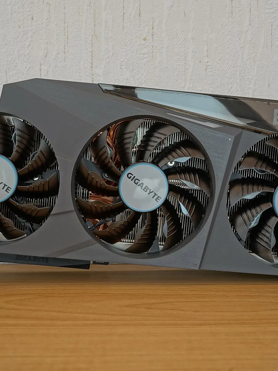
Where the Weight Actually Travels
A graphics card inserted into a PCIe x16 slot is essentially a beam fixed at one end. The connector’s gold fingers and the slot’s internal contacts are the fulcrum, and everything from that point forward—the printed circuit board, the components soldered to it, the traces buried in the laminate—becomes part of the load path. A datasheet describes a professional graphics card that uses a PCI Express 3.0 x16 system interface, and a specification sheet confirms that x8 and x16 cards rely on edge contacts whose mechanical form factor is standard height, three-quarter length, and double slot. Neither document describes those interfaces as load-bearing elements.
The IDC-Online reference explains that long-lasting permanent loading and cyclic loading are well-documented mechanisms for damaging solder joints. Bending, tearing, or peeling forces can cause the adhesive bonds between solder lands and the printed-board laminate to yield before the soldered connections themselves, especially when components on single-sided boards are loaded in compression or subjected to bending. A graphics card hanging off a vertical motherboard experiences exactly that bending—day after day, through power cycles and thermal expansion, the joint regions at the slot interface and near the memory chips absorb stress that the original design did not intend them to carry.
What Stress Does to the Board Over Time
The failure mechanisms already catalogued in electronics reliability literature translate directly to a sagging GPU. The IDC-Online reference identifies permanent loading as one culprit, and a white paper from EKWB on temperature cycling and fatigue in electronics states that the majority of failures in that domain are caused by thermo-mechanical loads, with solder fatigue being the dominant failure mechanism. The same paper notes that the difference in coefficients of thermal expansion between components and the printed board creates strain in solder and embedded copper structures, and that strain can induce fatigue failure. A card that already lives under a constant bending moment enters each heating cycle with a pre-existing stress field, so the cyclical loads that eventually crack solder balls are superimposed on a static deflection they were never intended to see.
A research paper adds detail: compressive stress at the end of a solder joint can be extremely high, leading to local plastic deformation, signal drift, and cyclic fatigue problems. The same paper warns that the maximum tensile stress inside the joint raises concern for long-term loading at high temperature because of potential creep failure. Creep—time-dependent deformation under constant load—means a card that looks fine for a year can develop latent damage at the molecular level that never heals. Visual sag is merely the external symptom of that internal creep.
Why Stiffness and Joint Geometry Matter
The EPFL paper measured solder-joint strength and found that a joint can withstand bending moments up to about 2 N before both joint and cantilever strength become critical. Two newtons is not a large moment; a long, heavy card generates far more leverage at the slot simply through its own mass multiplied by distance. An analysis of solder stress in electronic packages explains that stiffer printed-board designs and smaller packages can improve solder-joint fatigue life, and that solder stresses induced by random vibration loading are reduced in shorter joints. The implication is stark: a flexible full-length card with a modest heatsink creates a longer lever arm and a larger bending moment than a shorter, stiffer card of equal weight. The same card in a smaller, tighter case may fare marginally better because the board sees less vibration, but the creep-inducing static load remains.
Geometry also determines where the stress concentrates. The soldered contacts closest to the slot edge are the first to feel the peeling force. If the card’s printed circuit board has any pre-existing micro-voids in the laminate or the copper pours, the bending load can turn those voids into crack initiation sites that grow under thermal cycling. The result is rarely a sudden, catastrophic failure; it is more commonly a slow degradation of signal integrity that manifests as intermittent crashes or lanes dropping out, symptoms that most users blame on drivers or power delivery.
What Support Actually Changes
Not all supports do the same work. A GPU support-bracket product page from Mnpctech describes a design that mounts using two open PCI slots below the card and is intended to support heavy graphics cards by transferring load into the chassis. A bracket page from ColdZero adds that its bracket includes a spacer block to move the support point closer to the card’s edge, so the bracket can bear the card’s weight more effectively. These designs convert the cantilever problem into a two-point support system, moving the bending load away from the slot’s edge fingers and into a rigid metal frame that attaches to the case.
A simple vertical pillar placed under the shroud does not do this. It pushes upward, but it often contacts the cooler’s plastic housing or a non-structural part of the shroud, and it rarely provides a consistent counter-moment. The slot edge may still carry most of the weight, and the pillar can introduce a point load that bends the card locally if positioned poorly. The distinction matters because a brace that genuinely moves the load into the case relieves the soldered joints; a prop that only makes the card look level leaves the same stress path intact with a slightly different angle.
How to Assess a Heavy Card
A practical assessment draws on the physical principles in the sourced documents. The steps are cautious and source-backed, not a formal test, but they align with what the published materials describe:
- Examine the card from the side with the system off and the case horizontal. Look for any visible deflection along the length of the printed circuit board, particularly near the slot edge.
- Check whether the card relies solely on the PCIe slot and its locking tab. The NVIDIA datasheet and the PCIe specification sheet both describe the slot as a signal interface, not a weight-carrying structure.
- Consider the card’s length and cooler mass. A longer card with a heavy three-slot cooler creates a higher bending moment at the fulcrum, based on the lever principle corroborated by the EPFL bending-moment data.
- Prefer a support that transfers load into the chassis. A bracket anchored to the PCIe slot area below the card, as described on the Mnpctech product page, moves the load into the case frame; a spacer that positions the support near the card’s edge, as shown in the ColdZero page, improves the mechanical advantage.
- Avoid supports that contact only the shroud or that rely on friction pads under the card without a rigid connection to the case. The difference is between unloading the slot and simply altering the appearance of sag.
The investigation that is still missing—and that neither the retrieved standards nor the vendor documents provide—is a formal limit on allowable deflection, bending moment, or force for an installed PCIe card. Until such a specification is published, the conservative approach treats any visible sag as a warning that the card’s own weight is working against the very joints that keep it electrically alive. A bracket that opens a second load path into the chassis costs little and addresses the physics that the solder-joint literature makes plain; a stick that only props up the tail does not.