CRT versus modern panels: where the latency actually goes
A cathode-ray tube display does not wait for a whole frame to arrive before it starts painting the screen. It fires electrons the moment the first line of video data is ready, tracking the signal from left to right, top to bottom, with no pause to collect and store. A modern flat-panel monitor, even a fast one, almost always holds at least one complete picture in memory before the backlight gets the instruction to turn on. That architectural gap – between a live scan and a buffered replay – is where the latency that competitive players and retro enthusiasts notice actually accumulates. Pixel response times, which the marketing sheets quote in single digits, explain only a fraction of the delay. The rest is processing and buffering, and much of it can be cut down if you know where it lives.
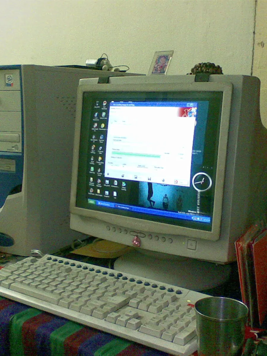
CRT scanout, not storage
A timing specification covers common computer displays – cathode-ray tubes and flat panels alike – setting the coordinated refresh rates, resolutions and blanking intervals that let a graphics card talk to a screen. In a CRT, those blanking intervals are not dead time but the moments when the electron beam slews back to the start of the next line or the top of the next field. The beam is always moving; its position dictates which phosphor dots glow at any instant. This is the foundational difference: the image is built in real time, scanned out in raster order exactly as the signal dictates. Some basic liquid-crystal displays mimic this behaviour, refreshing in lockstep with the input and updating pixels progressively from top-left to bottom-right. More elaborate panels, however, intercept the signal and hold scanlines or even full frames in a memory buffer to perform scaling, motion smoothing or colour processing before anything is shown. Where a CRT can begin lighting up a new frame within microseconds of the vertical sync pulse, a modern screen of that second type will not show a single new pixel until the buffer has been filled and the processing pipeline has run its course.
The three delays people call “lag”
When a gamer speaks of “input lag,” the phrase often collapses three distinct mechanisms into one. Separating them is essential, because only two are truly about delay, and only one of those is widely adjustable.
Processing latency is the time the display’s electronics spend interpreting the incoming signal, converting it to the panel’s native format, and applying any enhancements. Frame buffering is the intentional storage of one or more complete pictures, usually to permit motion-compensated interpolation or to synchronise the display with a different output clock. Pixel response time is the physical transition of a liquid-crystal cell from one brightness state to another, typically measured from black to white or between grey levels.
| Delay component | What it measures | CRT behaviour | Flat-panel behaviour |
|---|---|---|---|
| Processing latency | Signal conversion and enhancement time | Negligible (analogue path) | Varies with mode; game mode strips most processing |
| Frame buffering | How many full frames are stored before display | Usually zero; scans as signal arrives | From a few scanlines to several frames, depending on features |
| Pixel response | Time for a pixel to change colour | Phosphor decay is near-instantaneous but persistent | Millisecond-range transitions; specified but not the same as total lag |
A pixel that takes three millseconds to switch from grey to grey will still be the last thing to move if the display has already queued a dozen millseconds of processing and a full frame of buffering. The panel’s response number is a subcomponent; the total “feel” depends on everything upstream of the liquid crystal.
What a frame buffer is, and why it costs time
A controller data sheet describes a frame buffer as an area of memory holding enough encoded pixel values to fill the entire screen one or more times. The same documentation details a pixel data buffer containing exactly one encoded value for every pixel on the display. That architecture is not an accident – it is the standard way to decouple the incoming video signal from the physical panel refresh, giving the controller room to scale, rotate or post-process the image.
The cost is latency. Even a simple single-frame buffer, common in the cheapest office monitors, means the display will not begin to draw until the last pixel of that frame has been written into memory. If the signal arrives at sixty hertz, that is a wait of several milliseconds before any electron or liquid-crystal responds. Add motion interpolation or a multi-frame noise-reduction algorithm, and the buffer grows to two or three frames. A CRT, by comparison, needs no buffer at all: the video signal is the drawing instruction, and the beam follows it directly. The only storage inside a tube display is the persistence of the phosphor itself, which fades within a fraction of a millsecond after the beam moves on.
What CRTs do not transfer to a flat panel
A tube’s low latency is often conflated with its motion clarity, but the two are not the same. The short illuminated window – each pixel glows only briefly as the beam strikes, then dims rapidly – gives CRTs a crispness in moving scenes that early liquid-crystal panels could not match. That is a persistence advantage, not a lag advantage. Persistence determines how much motion blur the eye perceives; lag determines how quickly a user’s action registers on screen.
Modern panels can attack persistence through backlight strobing or black-frame insertion, which flash the backlight only when the liquid crystal has settled, effectively shortening the lit interval. Those techniques reduce blur, but they do not shorten the processing chain or empty the frame buffer. A monitor that strobes its backlight can still be holding a complete frame before it flashes. The tube’s lag advantage comes from the absence of that holding, not from the pulse of light. Recovering one does not automatically recover the other.
Turning down the delay on a modern panel
The single most effective step a user can take is to switch to the display’s game mode, if one exists. Game mode typically disables motion interpolation, advanced scaling and multi-frame noise reduction, collapsing the processing pipeline to something close to a simple line buffer. Some panels also offer a “PC” input label that bypasses the colour-enhancement and overscan logic otherwise applied to video sources.
Beyond that, turning off any remaining frame-creation features – smooth-motion settings, film-mode detection, dynamic contrast – forces the controller to pass the signal with minimal interference. The result is rarely a true zero-buffer scanout, but it can bring total lag down to a small number of milliseconds, at which point the remaining difference from a CRT becomes perceptible only in the most demanding applications. The pixel response time printed on the box, meanwhile, is a fixed physical property and has nothing to do with any of these settings.
The distinction that matters most for anyone trying to reduce lag is not between tube and liquid crystal but between live scanout and buffered playback. Modern panels can close much of that gap through a clean signal path. What they cannot borrow from a CRT is the sheer brevity of the pixel flash, and that is a visual property, not a temporal one. A low-lag flat panel and a low-persistence flat panel are not the same device, even if the marketing seldoms separates them. Keeping that division clear is the only way to know what you are actually chaising when you turn off the picture processing.